Deaerator unit (deaerator) – design features of the deaerator and operating principle
Deaerator (Deaerator) – deaerator design features, deaerator operating principle, deaerator column operation, water deaerating methods, post-deaerating water requirements all this and much more can be found in this article.
“A deaerator is designed to remove gaseous impurities from a coolant. It can also be considered a mixed-mode heat exchanger, as it heats and boils the coolant, from which non-condensable gases are removed using thermal energy…”
Deaerator.
Description and design.
The deaerator is designed to remove gaseous impurities from the coolant. It can also be considered a mixed-flow heat exchanger, as it heats and boils the coolant, from which non-condensable gases are removed using the thermal energy of the steam.
The water fed to the deaerator may contain various impurities: gaseous (oxygen, carbon dioxide, nitrogen, ammonia, and radiolytic and noble gases added to these after passing through the reactor core), solid (corrosion products of structural materials), and natural (chlorides, silica, and others).
Let’s consider the pathways for impurity entry during boiler or turbine operation. Gaseous impurities enter primarily through air leaks along the duct, as well as in equipment operating at subatmospheric pressure. Corrosion products enter the water as a result of the interaction of structural materials with the aqueous medium, forming metal oxides and their transfer into the water. Natural impurities enter primarily in the steam turbine condenser due to cooling water leaks in the heat-exchange surface. The cooling water pressure is always higher than the condensing steam pressure in the condenser, and if there are leaks, cooling water flows into the condensate. Cooling water leaks are practically always present, even if the condenser is factory-installed with a sufficiently tight seal. During operation, corrosion, erosion, and other processes cause leaks, increasing the amount of cooling water leaks. Cooling water is consumed in large quantities (the reservoir is designed for this purpose) and is not subjected to any pre-treatment. Therefore, even minor cooling water leaks introduce significant amounts of impurities.
Corrosion products, as well as some natural impurities (such as calcium and magnesium), precipitate as deposits on heat-transfer surfaces, reducing the heat transfer coefficient and causing localized, more dangerous types of corrosion damage to form beneath the deposits. This reduces the efficiency, reliability, and safety of the boiler house, thermal power plant, or nuclear power plant.
Of the gaseous impurities, oxygen and carbon dioxide pose the greatest danger.
The ingress of carbon dioxide through air leaks is insignificant. It is formed in the condensate-feed system due to the thermal decomposition of bicarbonates entering with process water, followed by the hydrolysis of carbonates.
Example of a chemical reaction:
![]()
decomposition: hydrolysis:
![]()
Oxygen and carbon dioxide are corrosive agents.
To reduce corrosion, HDPE heating surfaces are often made of corrosion-resistant materials such as brass alloys, austenitic stainless steels, and high-nickel alloys.
To manufacture HDPE from cheaper carbon steels, it is necessary to remove corrosive gases from the water, primarily oxygen and carbon dioxide. For this purpose, a deaeration unit is used, dividing the entire flow path from the condenser to the separator drum into condensate and feed paths.
Water deaeration methods and deaerator design.
Chemical and thermal methods can be used to remove gases from water. Chemical methods are based on the selective interaction of the removed gases with metered reagents. In practice, the chemical method is only applicable for oxygen removal. Hydrazine is used for this purpose, not as a standalone method, but to remove trace amounts of oxygen. Hydrazine can introduce other impurities into the water along with it. Furthermore, hydrazine is toxic. Thermal deaeration is primarily used at thermal power plants and nuclear power plants. Thermal deaerators remove any dissolved gases from the water without introducing any additional impurities.
Let’s consider the operating principle of a thermal deaerator:
According to Henry’s Law, the amount of a gas dissolved in water, such as oxygen (GO2), is proportional to the partial pressure of that gas above the liquid.
Where:
- Go2 is the amount of oxygen dissolved in water;
- ko2 is the coefficient of oxygen absorption by a liquid or the oxygen solubility coefficient, which depends on temperature;
- Po2 is the partial pressure of oxygen above the liquid.
Total pressure above water level:
Where:
- РН2О is the partial pressure of water vapor;
- SPг is the sum of the partial pressures of gases other than oxygen dissolved in water.
Taking into account (2), equation (1) can be written as:
Heating water can reduce oxygen content because the solubility coefficient (ko2) decreases with increasing temperature. Despite the decrease in oxygen content in water with increasing temperature, a significant amount remains. For example, as water temperature changes from 20 to 50°C, the amount of dissolved oxygen in water decreases from 9 to 5 mg/kg. The remaining oxygen (5 mg/kg) is hundreds of times higher than permissible levels.
From equation (3), it follows that for oxygen content in water to decrease to zero, the following condition must be met:
This condition is met when the water temperature rises to saturation temperature, i.e., boiling point. At boiling point, the pressure above the water is determined by the saturated vapor pressure of water, and the amount of dissolved oxygen in the water is zero.
To reliably remove gases from water, it is necessary to heat the entire water mass to saturation temperature. Underheating the water by 1–3°C increases the residual gas content in the water.
To meet condition (4), it is necessary to continuously remove the gases released from the water. The steam-gas mixture removed from the deaerator is called flash. The greater the flash, the more efficient the deaerator will be.
Deaerators can be mixed, surface, or superheated water. Mixed deaerators are the most widely used. Surface deaerators are used when the heating steam alters the material balance of the plant. For example, surface deaerators are installed in the primary circuit makeup lines of NPPs with WWER-1000 reactors. In superheated water deaerators, the water fed to the deaerator is heated in a heat exchanger to a temperature exceeding the deaerator’s saturation temperature. Excess heat from this water is converted into vapor. A disadvantage of superheated water deaerators is the difficulty of simultaneously deaerating water streams with different enthalpies, which is why they have not found practical application.
Deaerators are classified by pressure: vacuum, atmospheric, and high-pressure. Vacuum deaerators are installed in the heating network’s makeup water supply, atmospheric deaerators are installed in the makeup water supply line, and high-pressure deaerators are installed in the main condensate flow.
The deaeration device itself consists of a deaeration column, in which heated water flows downwards, while heating steam is supplied from below. The deaeration column is installed on the feedwater accumulator tank, where the deaerated water flows. In operation, a deaerator is defined as a combination of deaeration columns and the deaeration tank on which they are installed. To improve the deaeration process in mixing-type deaerators, it is necessary to provide a large contact surface between the heated medium and steam. Therefore, thermal deaerator designs are classified primarily by the method of water fragmentation. Deaerators are classified as nozzle, packed, film, jet, and bubbler deaerators. In nozzle deaerators, water is atomized using nozzles. Nozzle, packed, and film deaerators are not widely used because nozzle deaerators are ineffective, while packed deaerators (installation of a large number of metal packings) and film deaerators (water flows as a film along concentric steel rings) introduce additional corrosion products into the water. Jet deaerators, for example, are widely used at nuclear power plants. To increase the contact time of steam with water and the depth of bicarbonate decomposition, jet deaeration can be supplemented with bubbling deaeration, injecting some steam below the water level in the deaerator tank. The steam, bubbling through the water, promotes more complete gas removal.
General requirements for deaerators.
The capacity of the deaerator tanks is calculated based on the three-minute operation time of the feedwater pumps after the water supply to the deaerator is stopped. The water level in the deaerator must be maintained at a certain level and monitored using a sight glass. When the maximum permissible level is reached, excess water is drained through the overflow device. Increasing the level above the maximum permissible level impairs the operation of the deaerator column. The pressure in the deaerator must be maintained constant. This is because, after the deaerator, water heated to saturation temperature is fed by the feedwater pump into the feedwater main and then into the separator drum. A sudden change in pressure in the deaerator may cause the water to boil, which may lead to pump failure. As the turbine load changes, the steam pressure in the steam extraction lines will change, and the pressure in the deaerator will also change. If the turbine has adjustable steam extraction lines, the deaerator should be connected to this line. To ensure constant pressure, the deaerator is connected to several steam extraction lines of the turbine. Maintaining constant pressure in the deaerator disrupts optimal feedwater heating in stages. However, if the water entering the deaerator is underheated by 8–10°C, this effect is insignificant, and heating in the deaerator can be considered a general heating stage.
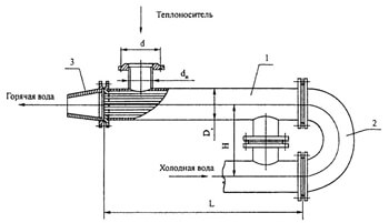
Design of deaerating column.
The deaerating column (see diagram) consists of a body, an annular receiving box, a mixing device, upper and lower blocks, and headers for heating steam and hot drainage streams.
The body is a welded steel cylinder with an internal diameter of 2408 mm, made of 12 mm thick sheet steel, to which a spherical cover is welded. The column body is welded to the deaerating tank (14).
At the top of the body is an annular receiving box (2) for receiving cold condensate streams. The inner shell of the box at the bottom has rectangular openings through which condensate enters the mixing device.
The mixing device (3) is designed to mix the cold condensate streams and distribute them evenly around the column perimeter. It is a box formed by the inner shell of the receiving box and the shell of the mixing device at the top, which has rectangular openings located around the entire perimeter.
The upper block consists of inner and outer shells and a perforated bottom (4) (perforated shield), welded to the bottom. To ensure structural rigidity and uniform condensate distribution across the entire surface of the perforated shield, six baffles with three half-holes at the bottom of each baffle are welded between the shells. The central portion of the upper block has a removable hatch, which is bolted to the annular projection of the perforated shield. The upper block is attached to the column body with six gussets arranged to allow free passage of steam around the periphery.
The lower block consists of an overflow plate (5) and a bubbling device. On one side, the overflow plate has a cutout for draining water into the bubbling device, and in the center, a neck (6) for the passage of steam. The overflow plate is secured to the column using a retaining frame.
The bubbling device consists of a perforated sheet (7), four drain pipes (8) welded to the side opposite the segmented cutout of the overflow sheet, a steam bypass pipe (9) extending 100 mm above it, a tray (10), and two water bypass pipes (11) connecting the bubbling sheet and the tray. The lower end of the steam bypass pipe is lowered into the tray, and when the tray fills with water, a water seal is formed. The water seal is filled automatically when the flow rate changes, by feeding water through the water bypass pipes from the bubbling sheet into the tray.
The heating steam supply manifold (13) and the hot drain stream collectors are located beneath the lower block.
The heating steam collector is a perforated pipe measuring 325 x 10 mm. The holes are arranged in seven rows along the bottom of the manifold, ensuring uniform steam distribution throughout the column.
The drainage supply manifolds are perforated pipes 108×6 mm, the inputs of which into the column are made at the same level as the heating steam manifold.
Scheme of deaerating column.

Description of the deaeration process in the column.
Cold condensate flows through the inlet nozzles (1) into the annular receiving box (2) and then through rectangular openings on the inner shell into the mixing device (3).
From the mixing device, upon reaching a certain level, the condensate flows uniformly around the entire perimeter to the perforated bottom (4) of the upper unit.
From the upper unit, the condensate passes through the openings in the perforated bottom and is broken into fine streams. Passing through the jet compartment, the condensate is heated to a temperature close to saturation and flows to the lower unit. First, it flows onto the overflow plate (5), then through a segmented cutout in the overflow plate onto the perforated plate (7) of the bubbling device. Water moves along the bubbling plate from left to right and is treated with steam passing through the openings in the shield. This heating to saturation temperature occurs, and dissolved gases are finally removed.
At the end of the bubbling sheet, water enters the lower part of the column through four drain tubes (8), the upper ends of which protrude 100 mm above the sheet to ensure a constant water layer. Water then flows through the drain neck (15) into the deaerator tank (14).
The drain neck ensures a constant water level at the bottom of the column before entering the deaerator tank. Water drains from the drain tubes below this level, preventing steam from passing through the drain pipes and bypassing the bubbling device.
Heating steam from the perforated manifold (12) is fed under the bubbling sheet. The degree of perforation of the sheet is selected such that, with minimal load, a stable steam cushion is created under the sheet, preventing water from falling through the sheet’s holes. Intensive steam treatment of the water layer moving toward the drain pipes, and deep and stable degassing, occurs on the bubbling sheet. Uncondensed steam and gases released from the water rise and enter the jet compartment through the neck (6) of the overflow plate.
As the steam output and flow rate increase, the pressure in the steam cushion increases, and the steam bypasses the bubbling plate through the steam bypass pipe (9) of the water seal and enters the jet compartment.
In the jet compartment, the steam, moving upward, intersects and washes the water jets falling downward from the perforated bottom. This process mixes the water with the steam, heating it to a temperature close to the saturation temperature at a given pressure in the columns, and pre-degassing the water. The condensate of the heating steam is connected to the water jets, and the uncondensed heating steam and gas released from the water pass along the periphery, through the annular gap between the body and the upper block, into the upper part of the column, providing its ventilation and heating of the counter-flows of water coming from the mixing device (3), and then through the steam outlet nozzle are removed from the column.