Steam Turbine Unit Design – Guidelines for the Course Project “Marine Steam Generators and Turbines”
This course presents practical calculation methods, taking into account the main design features of the flow paths of marine steam turbines and reheat turbines. Design features of high- and low-pressure turbines are highlighted. Approximate and refined stage calculations are provided, along with strength and vibration testing of the most stressed component of the flow path—the rotor blade. Methods for selecting the profiles and characteristics of nozzle and rotor blades are presented.
The course project should consist of an explanatory note and a graphical section (two drawings).
The calculation and explanatory note should contain:
- – Introduction;
- – Technical characteristics and brief description of the turbo-gear unit (TGU) design;
- – Preliminary thermal analysis of the entire turbo-gear unit at rated power, with determination of parameters at the beginning and end of the expansion process for each turbine casing;
- – Preliminary analysis of a given turbine (HP or LPT);
- – Detailed analysis with determination of all losses for a given stage;
- – Preliminary analysis of the main gear train;
- – Preliminary analysis of the main condenser;
- – Determination of the GGU weight;
- – Strength analysis of given turbine components with material data;
- – Conclusion;
- – List of references.
The explanatory note must be clearly written on one side of a standard-sized sheet of paper with margins of 30 mm on the left side and 10 mm on the right side, and must be provided with a table of contents.
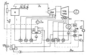
In addition to the calculation notes, the following are attached: a diagram of the heat transfer distribution between the turbine casings in the turbine control system, a steam expansion process in the i-s diagram and a profile of the solid section for a given turbine casing, a scaled-up i-s diagram of the steam expansion process for the calculated stage, velocity triangles, and a sketch of the flow path of the stage being calculated in detail, with nozzle and rotor blade profiles drawn.
The graphic portion of the project should contain:
- – a longitudinal sectional drawing of the turbine casing being calculated (high-pressure turbine or low-pressure turbine) (A1 sheet);
- – a drawing of the turbine assembly or component.