SECTIONAL HEAT EXCHANGERS
The name “sectional” indicates that these heat exchangers can be connected to create the required heat transfer surface. A sectional heat exchanger consists of one or more heat transfer tubes enclosed in a common casing. The heat transfer surface of a single section of industrial sectional heat exchangers ranges from 0.75 to 30 m², and the number of tubes per section ranges from 4 to 140.
The length of the tube bundle in a single section of a standard heat exchanger is typically 2 or 4 meters.
Tube-in-tube heat exchangers can also be classified as sectional heat exchangers. This type of unit (Fig. 1.1a) contains only one heat transfer tube, coaxially located within the casing. The heat exchanger is equipped with connections for the supply and discharge of coolants. One of them moves in the cavity of the inner pipe 2. The other coolant moves in the annular gap between the inner and outer pipes 1. The inner pipe may have longitudinal fins welded to it, either internally or externally, to increase the heat exchange surface on the side with the lower heat transfer coefficient.
The heat exchanger sections can be connected in series or parallel along the coolant flow path. Figure 1.1b shows a series connection of sections, both along the heating and the heated coolant flow paths.

Figure 1.1. Sectional heat exchangers.
The advantages of tube-in-tube heat exchangers include high heat transfer coefficients, suitability for operation at high coolant pressures, and ease of manufacture, installation, and maintenance. Disadvantages include low compactness, high cost due to the large metal consumption of outer tubes not involved in heat transfer, and difficulty cleaning the annular space between the tubes.
Tube-in-tube heat exchangers are primarily used for heating or cooling coolants in applications requiring relatively small heat transfer surfaces. They can also be used in processes involving boiling or condensing coolants. The advantage of tube-in-tube heat exchangers lies in their variety of configurations, and they can be quickly assembled on-site from standard components. If necessary, the heat transfer surface can be increased by installing additional sections. Control of coolant flow distribution across each heat exchanger channel is simplified, which is especially important when cooling viscous liquids, where a single pump can be installed for a group of heat exchangers if necessary.
The main disadvantages of tube-in-tube heat exchangers are their large volume and high cost per unit of heat transfer surface area. A further development of the sectional heat exchanger design are heat exchangers (Fig. 1.1b), whose housing 1 houses not a single tube, but a bundle of tubes 2. This type of unit is more compact than a tube-in-tube heat exchanger and, per unit of heat transfer surface area, is less expensive.
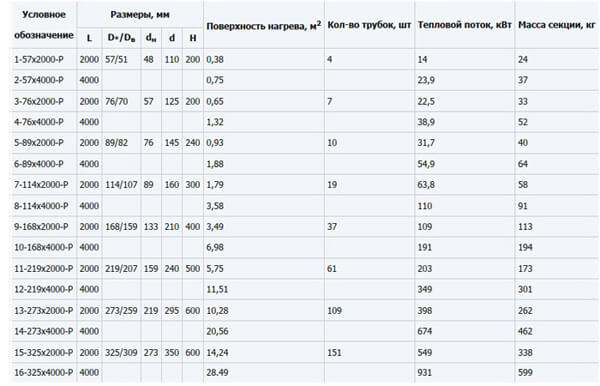
The design and main dimensions of standard sectional heat exchangers are shown in Fig. 1.2, and their technical specifications are in Table 1.1. The general arrangement of sections connected in series along both the heating and the heated coolant flow is clear from Fig. 1.3. The tube bundle is made of 16 x 1 tubes (the first number is the tube’s outside diameter, the second is the tube wall thickness).
The third column of Table 1.1 shows the ratio of the heat exchanger’s outer shell diameter D* to its inner diameter Dв.
It should be noted that in sectional heat exchangers, the tube bundle length is typically tens of times greater than the shell diameter. Therefore, only two coolant flow patterns are practical in them: co-current and counter-current.
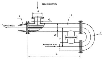
Figure 1.2. Main dimensions of sectional heat exchangers without a temperature expansion compensator: 1 — section; 2 — flanged flange; 3
— flanged adapter.
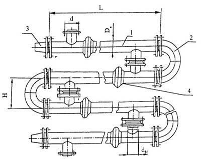
Figure 1.3. Layout of sectional heat exchangers with a temperature expansion compensator: 1 — section; 2 — flanged flange; 3 — flanged transition; 4 — expansion joint.
Table 1.1. Technical data of sectional heat exchangers